If you ever walked into my apartment, the first thing that you would notice would be the ubiquitous amount of plants. Children are too expensive, so my partner and I opt for owning plants instead. And there’s solid research on the positive effects that houseplants have on mental health . The onus of watering and general care is what typically keeps these plants alive. Of course, it’s such a pain to remember to check and water all of these plants (it really isn’t but I like to pretend it is).
So I decided to do what any engineer would do, and make like something overly complex just to automate a simple tasks. My goal was to build a sensor that would give me alerts for when my plants needed water. A wireless soil sensor with some sort of notification.
This was only my second major project with using the Arduino. And for background, my field is software engineering. So my knowledge of electronics doesn’t go past whatever I’ve learned in high school. Luckily, the arduino forums have been a huge help along with reddit and other online sources.I went through multiple iterations of this project before finally coming up with a PCB and the final app. Here’s the journey into building the wireless soil moisture sensors.
Architecture
Here’s the final architecture. In each plant, I have an Atmega328 that wakes up every 6 hours and transmits a soil reading and its battery level to a raspberry pi. The raspberry pi then uploads that data to Google Firebase. Using Firebase cloud functions, I detect if the battery gets too low or the moisture is dry. If one of those conditions are true, it sends a notification using Firebase Cloud Messenger to my custom built Android app which then notifies me. Here is the GitHub repo for this project .
Soil Moisture Sensor
I started off using by ordering these capacitive soil moisture sensors . The output voltage ranges from 0-3 volts. Through testing, I’ve found that the max voltage you could actually get in dry soil is around 2.5 volts. In wet soil, it can be as low as 1.4 volts.
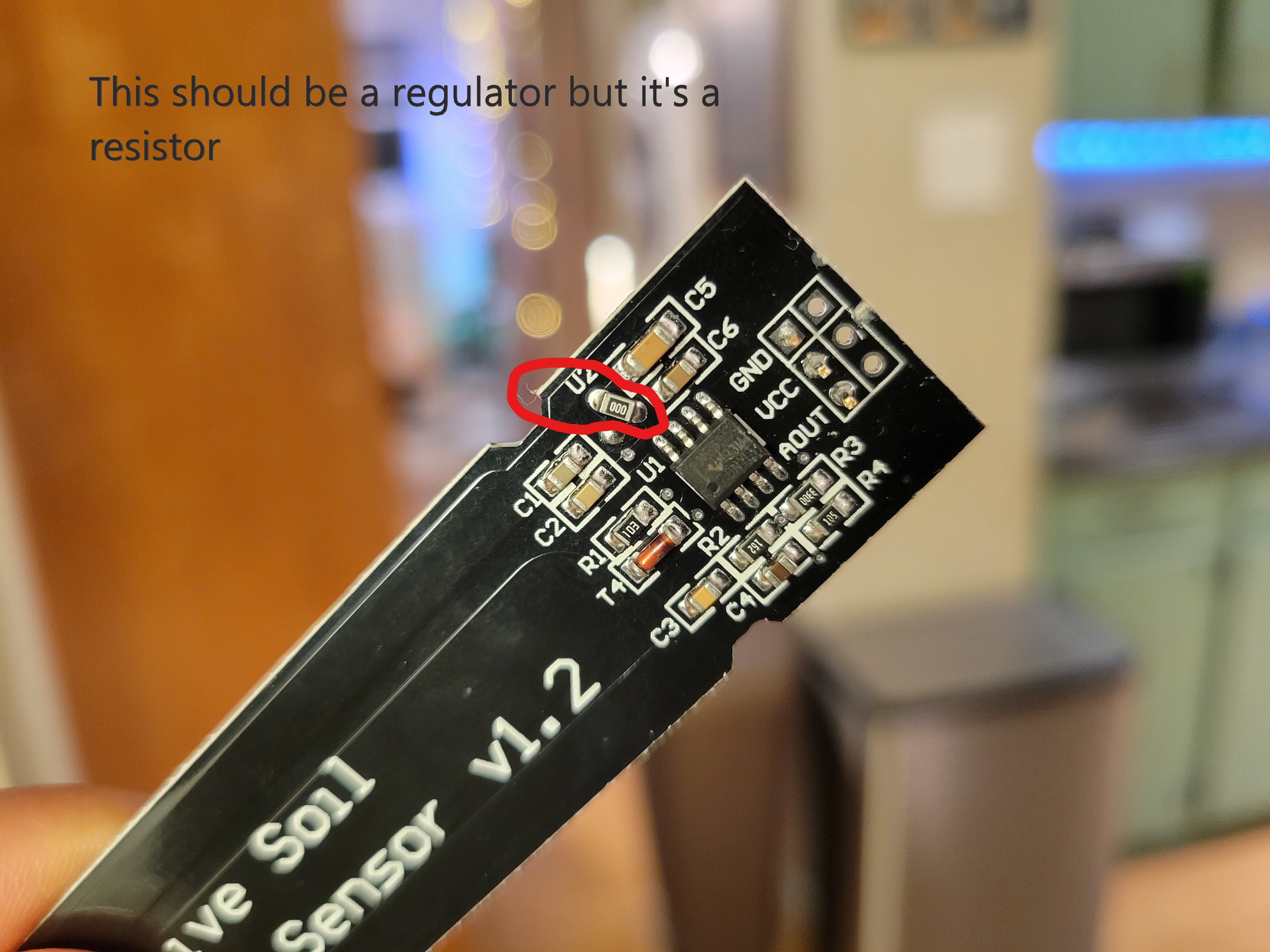
I tried to save money and order cheaper version of these from Aliexpress. However, to my disappointment, the cheap ones from Aliexpress lack a voltage regulator on the board. It’s just filled in with a resistor 🙄.
Wireless Communication
I tried a couple of different communication methods before settling on plain 433mhz transmitters.
2.4GHZ NRF24L01 Transceivers
I originally used the NRF24L01 2.4GHZ transceivers . The tricky thing about these things is that you need to remember to put a capacitor (around 10 uF iirc) between the power and ground pin. Other than that, these worked pretty damn well. Spectacular two way communication with acknowledge packets and pretty far distance (about the same distance as WiFI). Also the transfer speed goes up to 2Mbps. These would be great for RC cars or anything that needs fast communication with a modest range. And thanks to the Radiohead library for Arduino, it was also easy to get these working. You can find my original sketch for this on GitHub .
I decided not to go with these in the end because they felt like overkill! All I needed was something to send a couple of bytes of data twice a day.
WiFI (ESP8266)
My second approach was to try and use the ESP8266 for communication. Like the previous radios, this is also in the 2.4GHZ spectrum. For a moment, WiFI seemed like a good idea. I could connect these to AWS IoT and use their MQTT server to communicate with the device. AWS IoT also has a service called “device shadow” which I could use to report and set the state of the sensor. Additionally, I could connect it to multiple AWS services like AWS Lambda or AWS SNS and do more computation with the data. You can find my sketch for using the ESP8266 with AWS IoT on GitHub.
In the end, I decided not to go this route because of power consumption. WiFI drains a crazy amount of energy. Just turning on the ESP8266, waiting for DNS resolution and a connection to AWS IoT, could use as much as 300mAh. SUre, there are ways that I could possibly mitigate this power drain, but it still seemed like a bit overkill. Maybe for further products, I would like to explore this, but not right now.
433Mhz Radio
I finally settled on using these plain 433Mhz radio . These are “dumb” radios that just use ASK to send out a signal and that’s it. There’s no acknowledgement or high speeds. Just shoot your shot and forget. But these also drain very little energy. In hindsight, I wish I had not gone with these. Without attaching an external antennae, the distance is not impressive. I also had lots of “dropped” messages. Maybe from interference or something. It’s not a huge deal since my transmitter and receiver are in the same room and this isn’t a critical project. But still, more than 10 feet away and I lose signal. Also, I could not find a decent SMD version of these.
Arduino Board
I expiremented with a couple of Arduino boards before settling on the Atmega328p.
ATTiny85
I first wanted to use an ATTiny85 when I was planning on using the NRF24L01 transceivers. However, due to the limited amount of memory, it was nearly impossible to fit the RadioHead library and anything else on the ATTiny. It was just too unstable with barely no memory available.
ESP8266
WiFi power consumption too high and deep sleep mode was only rated at 20 µA. I wanted at most 10 µA for deep sleep. Also the weird thing with setting GPIO16 to ground or something confused me a bit. In hindsight, I have a better idea of how I could’ve implemented this with the ESP8266 while keeping power low. However, I still feel like WiFI would’ve drained too much energy for this project.
Atmega328p
This has everything I needed. Plenty of IO pins, less than 10 µA of current in deep sleep, and enough memory for the whatever I needed. And thanks to Nick Gammon’s tutorial , I was able to find ways to even lower the power consumption.
Voltage Divider and PNP Transistors
I learned a lot doing this project; such as measuring battery voltage. I learned how to use a voltage divider and feeding a reference voltage to the Atmega’s AREF. I also learned about how to use high-side switching to turn on and off things like a voltage divider and the soil moisture sensor. Using an NPN transistor, I can use it to drive a PNP transistor low and “activate” another pathway.
Schematic
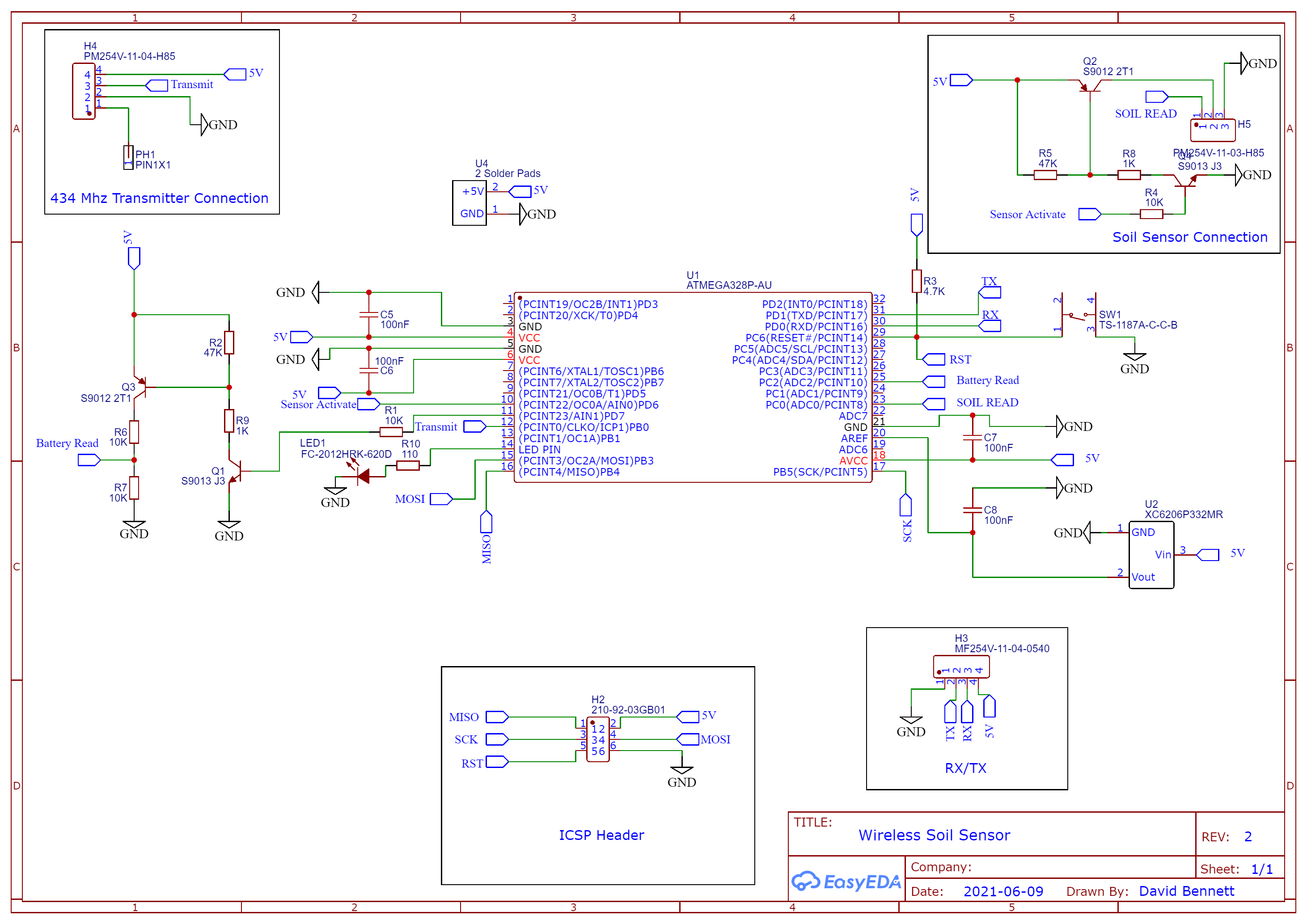
Here’s the final schematic. The Atmega328 is powered directly from the battery (4.5V). A stable 3.3v regulator is fed from the battery into AREF, and that is used to compare against for the other voltages. When the Atmega328 turns on, it takes a soil reading, reads the battery levels, then transmits the values to my server (Raspberry PI) and goes back to sleep for 6 hours. There’s a button to manually reset the device and trigger a reading. Also, an LED just to flash and indicate things are working. It takes about 1.5 seconds to complete it’s tasks. During operation it consumes about 12mAh. During sleep it consumes about 6.5 µA.
This was also my very first time putting a schematic together. I used EasyEDA for designing the schematic and the eventual PCB design.
Arduino Sketch
Here’s the final Arduino sketch. You can also check out the full
GitHub repo for this project
. Notice how I split up the bytes before sending them off. You can only send one byte (0-255) of data at a time. So I needed to do some bitwise operations in order to get the high and low values. Also, I used uint8_t types because of the Endianness of my Arduino versus my Raspberry PI (that is receiving the data). uint8_t is a fixed width integer so it is similarly represented on both architectures.
#include <RH_ASK.h>
#include <avr/sleep.h>
#include <avr/wdt.h>
#include <EEPROMex.h>

#define DEBUG 0 // Switch debug output on and off by 1 or 0


#if DEBUG
#define PRINTS(s)   { Serial.print(F(s)); }
#define PRINT(s,v)  { Serial.print(F(s)); Serial.print(v); }
#else
#define PRINTS(s)
#define PRINT(s,v)
#endif

//Data structure that we are sending
//We can only send 1 byte at a time, so 16 bit data needs to be split into high and low values
//That data will be joined back on the other side
///////////////////////////////////////////////////
 typedef struct
 {
     uint8_t   idLow;
     uint8_t   idHigh;
     uint8_t   mLow;
     uint8_t   mHigh;
     uint8_t   vLow;
     uint8_t   vHigh;
     uint8_t   firmware;
 } DataModel;
////////////////////////////

RH_ASK driver(2000, 11, 8, 10, false);  //(uint16_t speed=2000, uint8_t rxPin=11, uint8_t txPin=21, uint8_t pttPin=10,

const byte LED_PIN = 2;
const byte FIRMWARE_VERSION = 2;
const byte VOLTAGE_DIVIDER_PIN = 7;
const byte SENSOR_ACTIVATE_PIN = 6; //Turns on NPN transistor and Capactive Soil Sensor
const byte SOIL_MOISTURE_PIN = 0;
const byte VCC_VOLTAGE_PIN = 2;

const uint16_t SLEEP_COUNTER_MAX = 1800; // 4 hours == 14,400 seconds / 8 seconds per sleep = 1,800
const float AREF_VOLTAGE = 3300.0; //milivtols - Regulator is connected to Aref


uint16_t ID;
uint16_t sleepCounts = SLEEP_COUNTER_MAX; //starting it at max so we send on startup


void setup()
{
    resetWatchdog ();

    #if DEBUG
      Serial.begin(9600);
    #endif

    pinMode(LED_PIN, OUTPUT);
    pinMode(SENSOR_ACTIVATE_PIN, OUTPUT);
    pinMode(VOLTAGE_DIVIDER_PIN, OUTPUT);
    analogReference(EXTERNAL); //Connecting a 3.3v regulator to Aref
    randomSeed(analogRead(SOIL_MOISTURE_PIN));
    driver.init();

    //Retrieve ID information
    ////////////////////////////
    ID = (uint16_t) EEPROM.readInt(0);
    PRINT("\nRetrieved Chip ID: ",ID);
    if(ID == 65535){ //EEPROM address has not been written to most likely. Would use 255 if reading byte instead of int
      uint16_t newID = generateRandomID();
      EEPROM.writeInt(0, newID);
    }


   //Indicate that things are working
   ///////////////////////////////
    digitalWrite(LED_PIN, HIGH);
    delay(100);
    digitalWrite(LED_PIN, LOW);


}


uint16_t generateRandomID(){
  uint16_t id = (uint16_t) random(1000, 20000);
  PRINT("\nNew Generated is: ",id);
  return id;
}


//Samples ADC readings from a specific pin and returns the averag
//////////////////////////////////////////////
float sampleReadings(byte pin, byte samplesize){
   int totalReadings = 0;
   for(byte i =0; i< samplesize; i++){
    totalReadings = totalReadings + analogRead(pin);
    delay(10); //just pause a bit between readings;
  }
   float counts = totalReadings/(float)samplesize;
   return counts;
}


//Returns the  output Voltage of the capacitive soil sensor
/////////////////////////////////////
uint16_t getSoilReading(){
  float counts = sampleReadings(SOIL_MOISTURE_PIN, 25);
  PRINT("\nSoil Sensor Counts is: ",counts);
  uint16_t voltage = ((counts/1023.0)* AREF_VOLTAGE);
  PRINT("\nSoil Sensor voltage is: ",voltage);
  return voltage;
}


//Nick Gammon
//https://www.gammon.com.au/forum/?id=11497
///////////////////////////////////////////
void resetWatchdog (){
  // clear various "reset" flags
  MCUSR = 0;
  WDTCSR = bit (WDCE) | bit (WDE);
  // set interrupt mode and an interval
  WDTCSR = bit (WDIE) | bit (WDP3) | bit (WDP0);    // set WDIE, and 8 seconds delay
  wdt_reset();  // pat the dog
}  // end of resetWatchdog


//Nick Gammon
//https://www.gammon.com.au/forum/?id=11497
///////////////////////////////////////////
void enterSleep(){
  byte old_ADCSRA = ADCSRA;
  set_sleep_mode (SLEEP_MODE_PWR_DOWN);
  ADCSRA = 0;            // turn off ADC
  power_all_disable ();  // power off ADC, Timer 0 and 1, serial interface
  noInterrupts ();       // timed sequence coming up
  resetWatchdog ();      // get watchdog ready
  sleep_enable ();       // ready to sleep
  interrupts ();         // interrupts are required now
  sleep_cpu ();          // sleep
  sleep_disable ();      // precaution
  power_all_enable ();   // power everything back on
  ADCSRA = old_ADCSRA;   // re-enable ADC conversion

}

// watchdog interrupt
///////////////////////
ISR (WDT_vect)
{
   wdt_disable();  // disable watchdog
}


//Returns the  output Voltage of the battery
/////////////////////////////////////
uint16_t getBatteryVoltage(){
    float counts = sampleReadings(VCC_VOLTAGE_PIN, 25);
    PRINT("\nBattery Counts is: ",counts);
    uint16_t voltage = ((counts/1023.0)* AREF_VOLTAGE) * 2.0;
    PRINT("\nBattery Voltage is: ",voltage);
    return voltage;
}


void transmit(){
    DataModel data;
    uint16_t moisture = getSoilReading();
    uint16_t voltage = getBatteryVoltage();
    uint8_t idLow = ID & 0xff;
    uint8_t idHigh = (ID >> 8);
    uint8_t xlow = moisture & 0xff;
    uint8_t xhigh = (moisture >> 8);
    uint8_t vlow = voltage & 0xff;
    uint8_t vhigh = (voltage >> 8);

    data.idLow = idLow;
    data.idHigh = idHigh;
    data.mLow = xlow;
    data.mHigh = xhigh;
    data.vLow = vlow;
    data.vHigh = vhigh;
    data.firmware = FIRMWARE_VERSION;

    driver.send((uint8_t *)&data, sizeof(data));
    driver.waitPacketSent();

}


void loop(){
    if(sleepCounts >= SLEEP_COUNTER_MAX ){
      digitalWrite(SENSOR_ACTIVATE_PIN, HIGH);
      digitalWrite(VOLTAGE_DIVIDER_PIN, HIGH);
      delay(500); //this delay is necesary or else adc will be off
      transmit();
      digitalWrite(VOLTAGE_DIVIDER_PIN, LOW);
      digitalWrite(SENSOR_ACTIVATE_PIN, LOW);
      sleepCounts = 0;
    }
    enterSleep();
    sleepCounts++;

}
Raspberry PI Receiver
On the Raspberry Pi, I connected the receiver part of the 433Mhz kit from earlier. I installed pigpiod so it provides me an interface to communicate with the GPIO on the Raspberry Pi. I then created the following program to listen for values and upload them to Google Firebase.
import piVirtualWire.piVirtualWire as piVirtualWire
import time
import pigpio
import struct
from datetime import datetime
import firebase_admin
from firebase_admin import credentials
from firebase_admin import firestore

pi = pigpio.pi()
rx = piVirtualWire.rx(pi, 18, 2000) # Set pigpio instance, TX module GPIO pin and baud rate

# Need to replace with your own firebase-keys files
cred = credentials.Certificate('/home/pi/firebase-keys.json')
firebase_admin.initialize_app(cred)

db = firestore.client()


def insertIntoDatabase(id, moistureValue, voltage):

	post_data = {
    		'id': id,
    		'moisture': moistureValue,
		'battery': voltage,
		'timestamp': firestore.SERVER_TIMESTAMP
	}

	doc_ref = db.collection('plants').add(post_data)

while True:

		while rx.ready():
			values = rx.get()
			print(values)
			idLow = values[4]
			idHigh = values[5]
			xlow = values[6]
			xhigh = values[7]
			vlow = values[8]
			vhigh = values[9]
			# We need to use bitwise operations to rebuild the original value
			id = (idHigh << 8) & 0xFF00 | idLow & 0x00FF
			moistureValue = ( xhigh << 8 ) & 0xFF00 | xlow & 0x00FF
			voltage = (vhigh << 8) & 0xFF00 | vlow & 0x00FF
			print(f'Moisture Sensor {id}  has a reading of  {moistureValue} milivolts  with a battery voltage of {voltage} ')
			insertIntoDatabase(id, moistureValue, voltage)
		time.sleep(0.5)

rx.cancel()
pi.stop()
Finally, I created a service so that this program is always running:
[Unit]
Description=Soil Moisture Service
After=network.target pigpiod.service

[Service]
ExecStart=/home/pi/git/soil_moisture_sensor/start_soil_service.sh
WorkingDirectory=/home/pi/git/soil_moisture_sensor
StandardOutput=inherit
StandardError=inherit
Restart=always
User=pi

[Install]
WantedBy=multi-user.target
Firebase Cloud Function
I deployed a firebase cloud function which checks the moisture value and battery voltage anytime a new value is written to the database. It writes to a topic which my Android app listens to. You can find the repo for this code here .
const functions = require("firebase-functions");
const admin = require("firebase-admin");

admin.initializeApp(functions.config().firebase);

/**
 * Sends to topic
 * @param {String} topic
 * @param {Object} payload
 */
function sendToTopic(topic, payload) {
  admin.messaging().sendToTopic(topic, payload);
}

/**
 * Returns the plant name from the id
 * @param {number} id
 * @return {String}
 */
function getPlantFromID(id) {
  const mappins = {
    9466: "Pothos (Nadia)",
    16333: "Peace Lilly (Gav)",
    13043: "Aspidistra",
  };
  return mappins[id];
}

exports.checkValues = functions.firestore
    .document("plants/{id}")
    .onCreate((snap, context) => {
      const newValue = snap.data();
      const moisture = newValue.moisture;
      const voltage = newValue.battery;
      const id = newValue.id;

      const TOPIC = "plants";

      // If it's greater than 2700 then it's probably a false reading
      if (moisture > 1920 && moisture < 2700) {
        const payload = {
          notification: {
            title: `${getPlantFromID(id)} needs water`,
            body: `Sensor moisture is at ${moisture} millivolts`,
          },
        };
        sendToTopic(TOPIC, payload);
      }


      if (voltage < 3500) {
        const payload = {
          notification: {
            title: "Battery Low",
            body: `Sensor in plant ${getPlantFromID(id)} has low battery`,
          },
        };
        sendToTopic(TOPIC, payload);
      }
    });
Android App
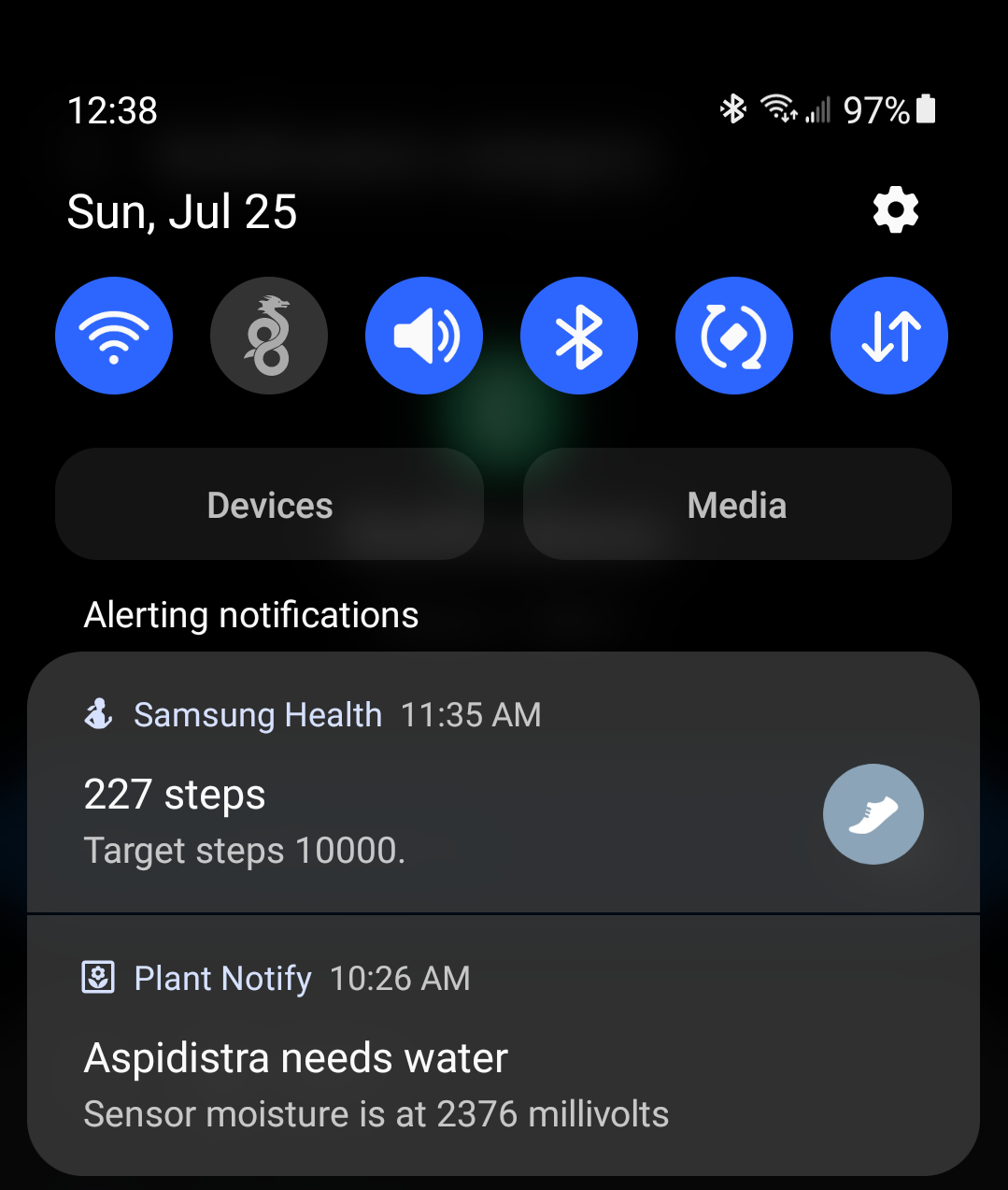
Finally, I wrote a custom Android app that send me a notification when it gets an alert from the Firebase cloud function. You can find the code for that project here .
Perfboard Prototype
Here is the original protoype. This prototype did not have the NPN-PNP drivers I mentioned earlier, but it still worked fine. I also discovered how much I hate soldering. I originally planned to solder 10 of these, but after doing one I was basically saying “fuck this” and decided to learn how to make a PCB.
Here is the prototype in my plant. I tested it there for 4 months.
PCB Design
The biggest part of this project was designing my own custom PCB. I have never done anything like this before, and relied purely on YouTube videos to help guide my way. I used EasyEDA to design the PCB and use JLPCB to order pre-assembled PCBs (I hate soldering lol).
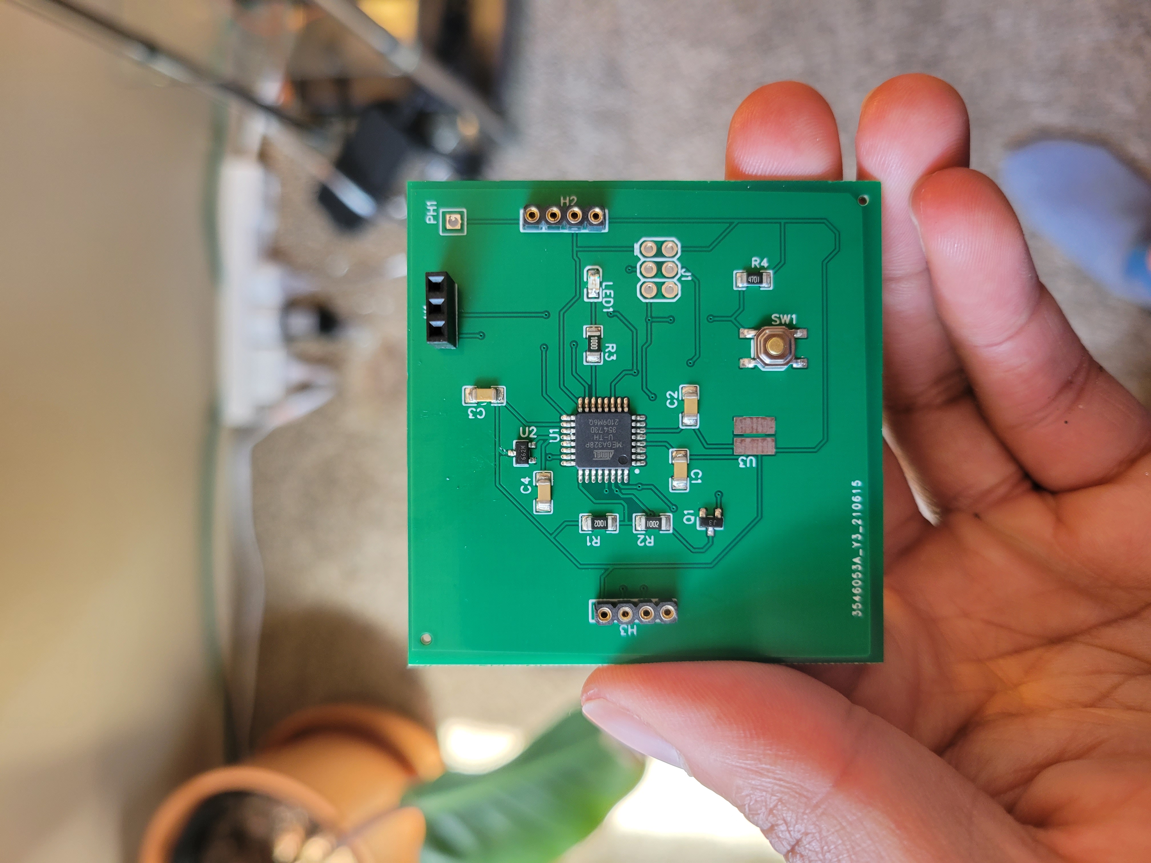
You can download the Gerber files and BOM over at the GitHub repo for this project . I’m still learning about PCB design and the right way to do it. This actually wasn’t my first iteration. I don’t have the Gerber files but for the first iteration it came out looking rough:
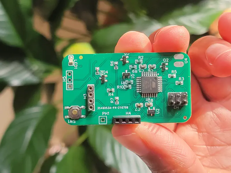
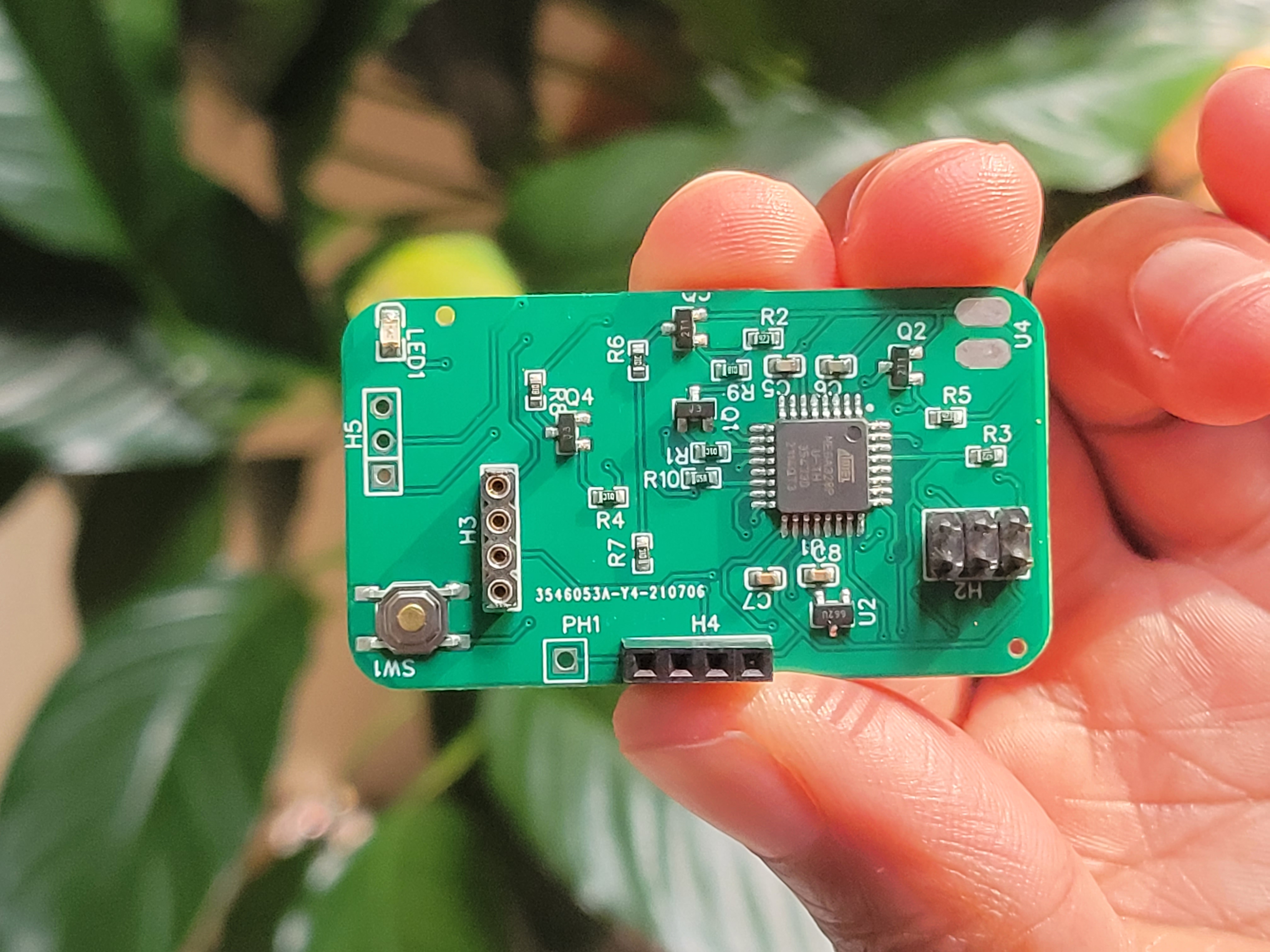
However, the final iteration came out looking legit (to me at least haha):
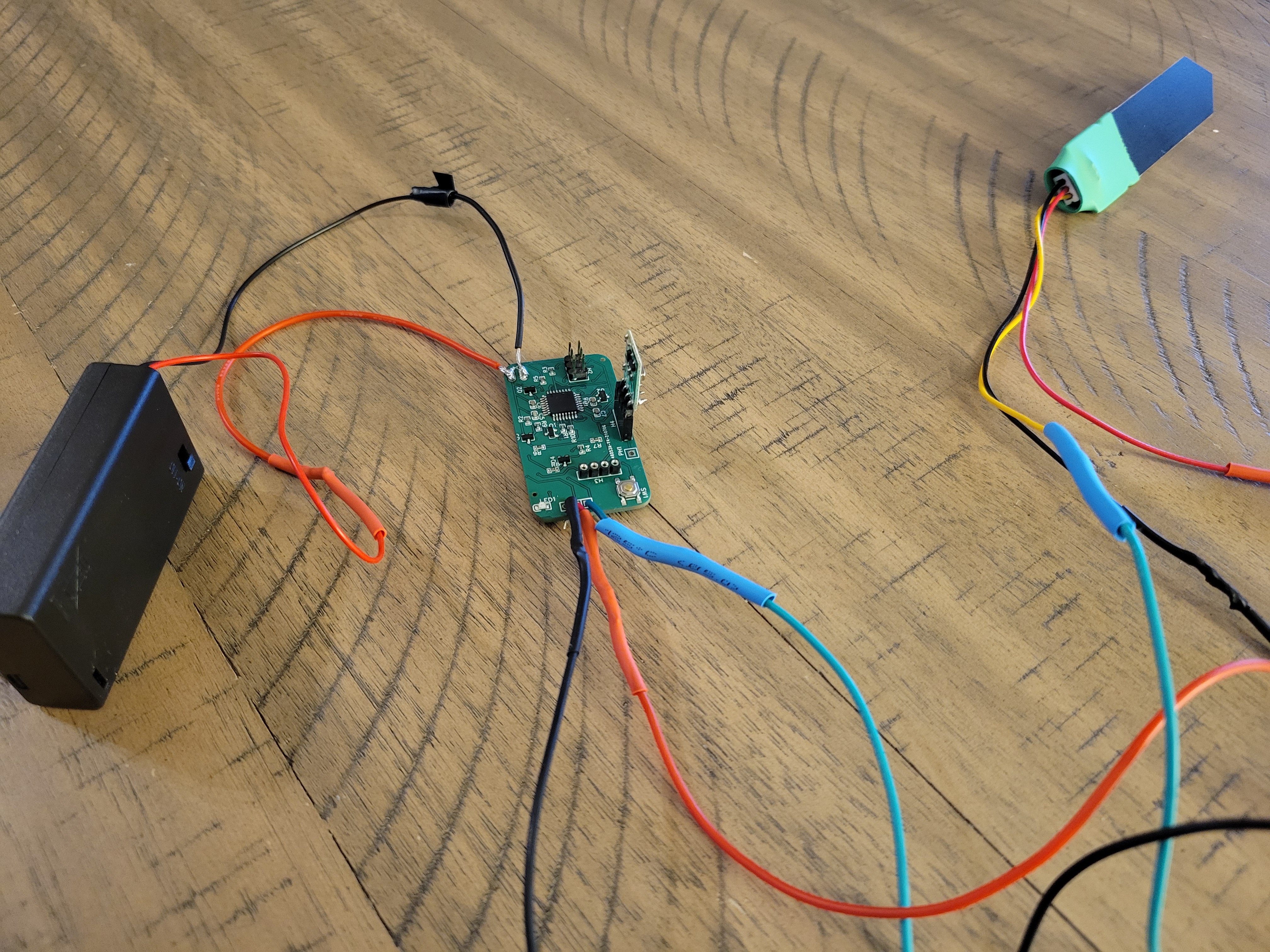
I made sure to add program headers, so that I was able to program the blank Atmega328-au onboard and flash the bootloader using an AVR programmer . And then I soldered on wires for the soil sensor and attached the 433Mhz radio (I couldn’t find an SMD version I liked). And here is what it looked like in the end.
Retrospective
This was my first big arduino project and it took me 7 months from starting this idea to coming up with the final PCB design. There were multiple points during this project where I lost interest and wanted to shelf it, but I’m glad I kept going. I learned a lot about electronics from this and have a cool thing to show people. As far as how well it actually works, well it’s not too bad. You have to make sure the soil sensor is positioned just deep enough to get a right reading, but not too deep where the top layer of the soil is going to be dry. The first few days were filled with experimentation and false positive alerts. But now things seemed to have settled.
If I were to do this project again, I would instead use low power BLE devices. Something like the NRF8240. They offer better range over my crappy radios, a more reliable connection and lower power consumption.
Links:
Soil_Moisture_Transmitter_Reciver Soil_Moisture_Notify_App fcm_soil_notification_function
